|
|
|
|
|
|
|
HDMI 1.4의 경우 14번핀을 사용하여 HEC DATA채널을 추가합니다.
HDMI connector pinout
The pin layout of the HDMI interface connector is shown in the figure below.
HDMI connector pinout
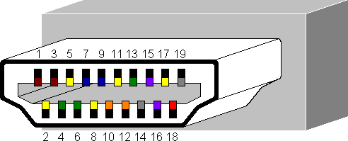
| Pin |
HDMI 1.0 |
New in HDMI 1.4 |
| 1 |
TMDS channel 2 + |
|
| 2 |
TMDS channel 2 shield |
|
| 3 |
TMDS channel 2 - |
|
| 4 |
TMDS channel 1 + |
|
| 5 |
TMDS channel 1 shield |
|
| 6 |
TMDS channel 1 - |
|
| 7 |
TMDS channel 0 + |
|
| 8 |
TMDS channel 0 shield |
|
| 9 |
TMDS channel 0 - |
|
| 10 |
TMDS clock + |
|
| 11 |
TMDS clock shield |
|
| 12 |
TMDS clock - |
|
| 13 |
CEC |
|
| 14 |
n/c |
HEC data - |
| 15 |
DDC I²C clock SCL |
|
| 16 |
DDC I²C data SDA |
|
| 17 |
DDC/CEC/HEC shield |
|
| 18 |
+5 VDC power |
|
| 19 |
Hot Plug Detect |
HEC data + |
| |


